Frequency Counter Nixie Clock
One upside to being a teaching assistant in physics labs is getting to dig through all the old equipment that has been hoarded. Running on limited budgets, it's not uncommon for lab technicians to stock-pile what is likely obsolete hardware. Who knows when you might be able to make it useful?
It's in this circumstance that I first layed eyes on a pair of old frequency counters. The Apti-Meter 361-R from Transistor Specialties inc. A beautiful fully solid state piece of kit from the 1960s! This baby can count at up to 1 mega-count-per-second - wowie!
 Importantly to me, the display of this device is a gorgeous set of six nixie tubes, which are increasingly hard to come by for a resonable price.
On one slow day I took the time to clear one of the counters out of the corner it was nestled in and plugged it in.
To my amazement - it was over 60 years old - it turned on as if no time had passed and all the digits flicked by in
 TEST mode.
I initally asked the lab manager if I could take the device and he sorta looked at me like I was crazy, it still worked after all!
So that's where things sat for a while, every semester I TAd the same lab course I would jokingly ask and get another no.
Then, it was my last year at the university, and the old lab manager was retiring soon, so I once again asked or should I say begged.
To my surprise, I was told "yeah sure why not", and then got a laugh when I asked if I could take both... So I ran away with my single frequency counter.
The Game Plan
Now the question was whthe boxat to do with it. In my at home life I don't have much use for a frequency counter. What else can we display with six digits? Well, I like clocks with seconds so HH:MM:SS works quite well! We could rip out the nixies and build a clock around them, but we already have display driving and number counting hardware, so why bother, let's just figure out how to get the display to accurate show the time down to a second.
Now there's a few ways we could do this. The one requiring the least intervention would be to feed in a signal with a frequency corresponding to the precise time. So at 12:46:64 we'd need a 124.664 kHz signal. Now I don't doubt that a modern microprocessor would have no problem generating up to the 239.999 kHz signal we'd need. However, displaying this time with no flicker in the last digit would require carefully synchronizing the signal generating machine with the frequency counter, and I doubt that synchronization would remain constant throughout the day.
Maybe before proceeding we should talk about how a frequency counter works. An input signal, say a sin-wave is first amplified to the point of clipping, giving us a square wave. Then, we simply need to count how many times this signal crosses zero within a given time period. If it crosses zero 100 times in a second then that's 100 Hz, or if it crosses zero 10 times in 1E-3 seconds then that's 10 kHz. So the frequency counter has two main components, a timer and a counter. The counter works by chaining flip flop gates together. In this case, six glorious base ten flip-flops. So the pulses from your zero crossing first increment the right-most nixie tube from 0-9, then as this tube rolls over to 0 the next digit is incremented by one, and so on. Then the flip-flops are gated by the timer so that they're only actively counting for the given span. Finally you simply read off the number of crossings on the display, and do some mental math to shift the decimal.
The reason we can't easily display the exact frequency is that the display resets every time it completes counting (after a small delay so you can read it). So if we start sending out a new signal one period before or after the timing starts, the output value will be off by one. At 240 kHz this requires an accuracy of 4 us, which I'm not sure our instrument will maintain.
So instead we can just drive the output ourselves! We know that if we send 40 pulses, it will show 40. Then we can keep track of the time and slowly increment the display by one every second. When we wrap around to minute we add an extra 40 pulses to go from 60 to 100, every hour we add 4000 pulses to go from 00:60:00 to 01:00:00, and when we hit midnight we can simply trigger the display reset to get 00:00:00.
Initial Teardown
Simple enough, but how do we actually do this? First we need to map out the internals, find where to send pulses and what not.
Let's start by opening up the device.
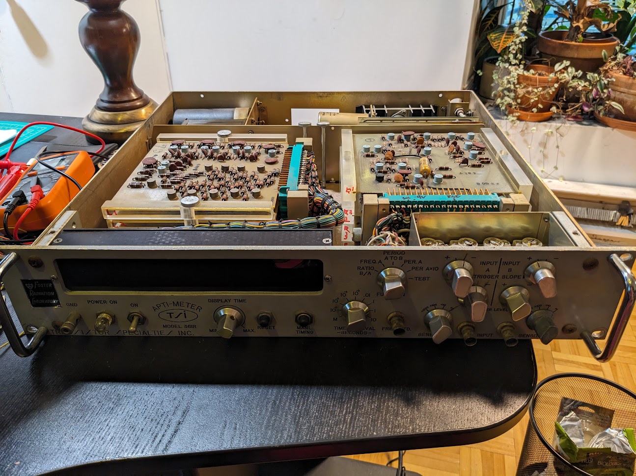 Right away, this thing is built in such an obvious manner that it's easy to get a sense for what's going on.
On the left there's a stack of cards attached by a massive umbilical chord to the dsplay section.
With six cards and six digits, we can assume that each one is in charge of driving it's own digit.
On the right, the input BNC's and knobs lead to a separate stack, so probably some input handling.
Then at the rear, the power plug goes into some large ICs, capacitors and transformers, so presumable power handling.
Fascinatingly, the cards are mounted on a swivel base, such that you can easily angle out the whole stack to remove lower cards.
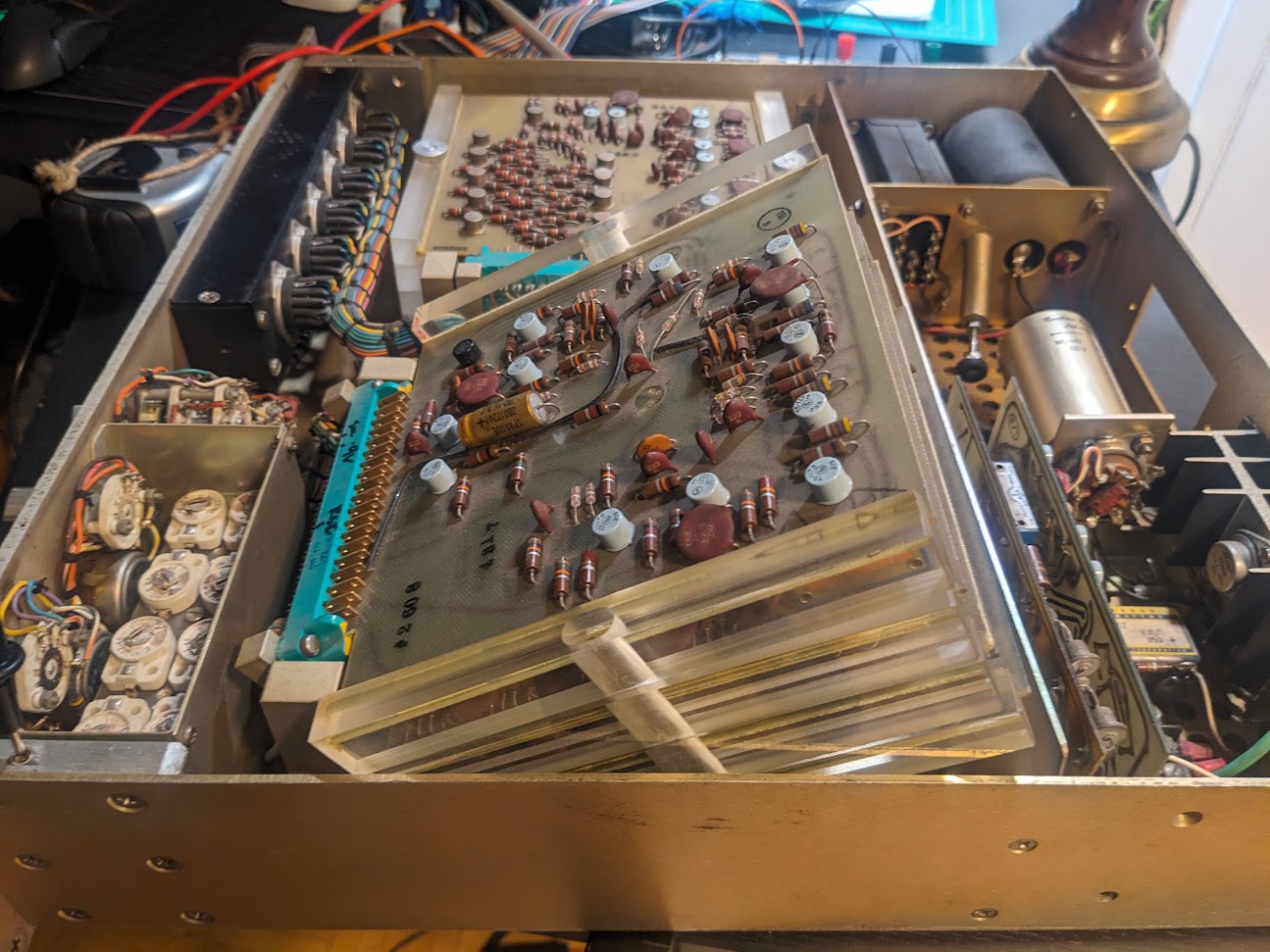
Now I stupidly went around poking and proding with a voltmeter while the device was plugged in, and of course I immediately sparked something on the top digit control
card and the whole thing stopped working properly in test mode...
Turns out, those cards keep delicate logic pins right next to the several hundred volt pins for directly driving the nixie tubes... oops.
Thankfully, I was able to trace the problem to one or two dead shorts in a transistor, but with little knowledge of the inner working, or of vintage transistors I wasn't sure how best to procede.
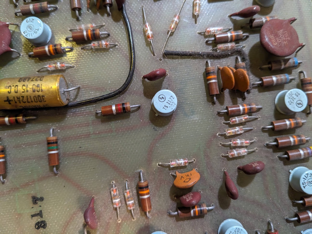 So I went to an excellent source for arcane knowledge, the EEVBlog forum with something as juicy as this I was certain I'd get some help.
Within a little over two hours, not only did I have my answer, but also a link to the full schematic and documentation for the device, eternally greatful for a network of nerds.

Thankfully from the given info and schematics, I was able to determine that the exact details of the transistors that I shorted weren't important, and they could easily be replaced by modern PNP transistors. A quick soldering later and it was counting like normal.
Theory of Operation
Getting my hands on the schematics was great cause I could now confirm my guesses.
 In a simple straight count mode each digit is chained to the next via a Decade Counter (DC-#).
By simply triggering the input, we could drive all numbers with a single wire.
Furthermore each decade counter has a reset, with all digits being wired to the same connection.
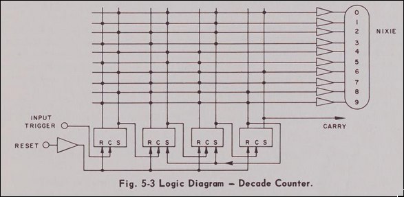
The last piece of the puzzle was how to get to the straight-count mode, as this is not directly selectable on the front panel. Through some experimentation it turns out that this is what they call the frequency count mode when you have an infintie display time and use the "Manual Time Base" button on the front of the panel. So we need some way to automate this.
Thankfully, the schematic of the top input board on the right side of the device answers all are questions
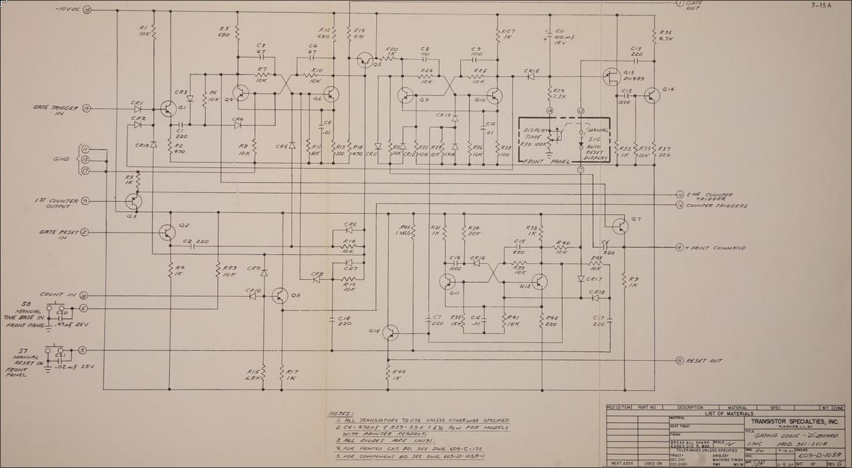 We see three inputs at the bottom left that are exactly what we're interested in:
- COUNT IN
- MANUAL TIME BASE IN
- MANUAL RESET IN
By following allong these connections, we can figure out that we simply need to ground each of these lines whenever we want to activate them.
Now here's where my lack of knowledge kind of bit me in the ass. I had some PNP transistors lying around and thought, okay so all I need to do is drive one of these with a microcontroller and then I can switch these negative voltages right? One dead ESP32 dev board later I realized I didn't really know how transistors worked. After a bunch of simulations and learning more about transistors, I opted to use some opto-isolators to avoid blowing up any more microcontrollers.
The electronics ended up being quite simple, I have an ESP32C3 dev board hooked up to the optoisolators and powered off of a usb charger that I hard wired into the power supply of the device.
In testing it looked like this:

I opted to code up the system in rust as I've been working on learning that. Thankfully, the ESP libraries allow for connecting to wifi and synchronizing to an NTP server, so my clock from the 60s can be super accurate! The main loop of the program ends up being quite simple.
#![allow(unused)]
fn main() {
let mut old_number = 0u32;
let mut new_number = 0u32;
let _ = reset(&mut rst_pin, &mut mt_pin);
loop {
    let time = Local::now();
    new_number = time_to_number(time, false, true);
    if new_number < old_number{
        let _ = reset(&mut rst_pin, &mut mt_pin);
        pulse(new_number, &mut tick_pin);
    }
    else {
        let delta = new_number-old_number;
        let _ = pulse(delta, &mut tick_pin);
    }
    delay::FreeRtos::delay_ms(50);
    old_number = new_number;
 }
}
We simply get the time, convert it to a decimal number i.e. 12:43:32 -> 124332 and then give it the number of pulses needed to get there. Occasionally the display picks up an extra tick from noise, so to deal with this i have the clock reset at midnight by checking for when the number goes down instead of up. This is also helpful upon start up as it takes a bit of time for the synchronization to kick in. I'll hopefully get around to writing up a seperate page on the coding for this thing, it was also fun, but will balloon this long text out even more.
With that setup, it somewhat perfectly works!
Here's a comparison to time.is
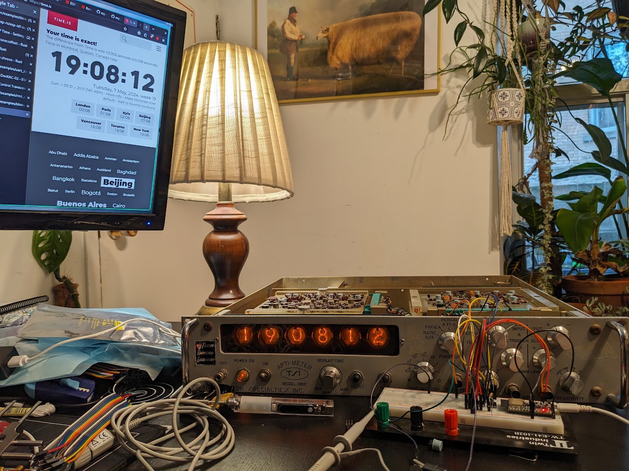
It now lives on my shelf of obsolete technology, along with my oscilloscope that visualizes the music playing on my sound system.
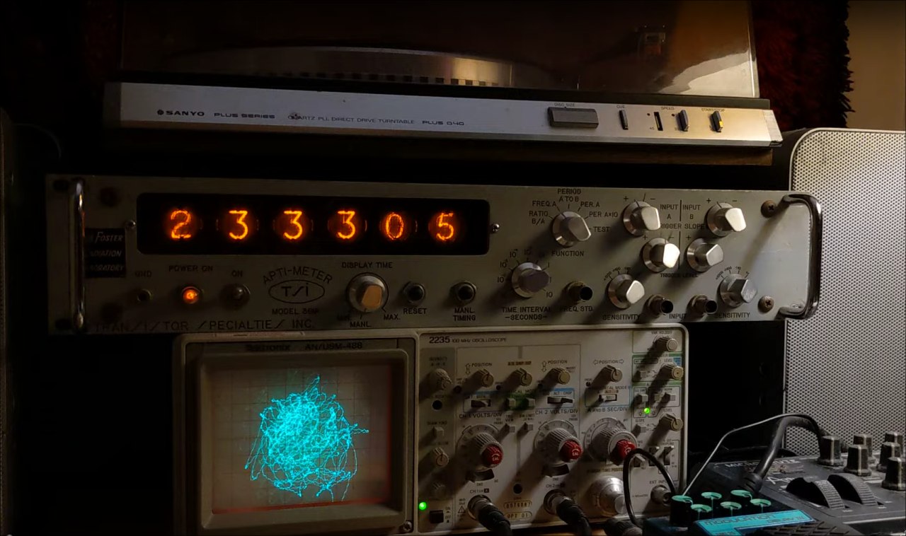 It's a great conversation starter, surpsingly few people immediately recognize it as a clock, but almost everyone compliments it.